
Description
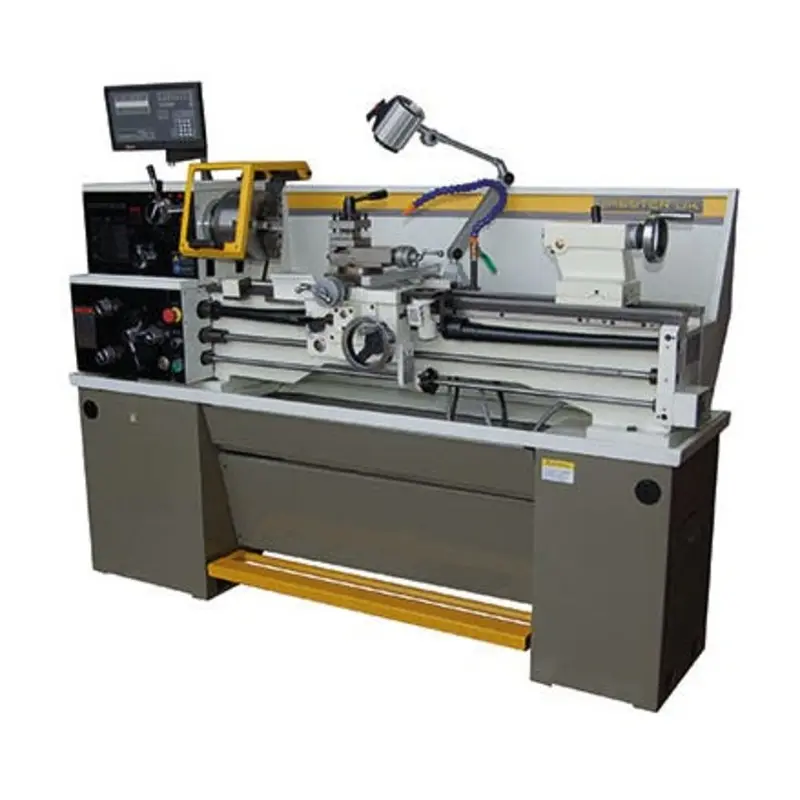
Chester UK Coventry Deluxe Lathe – Single Phase – 240V Product Description
The Chester Coventry Deluxe Lathe is a high-performance manual lathe that has been designed for precision machining in workshops and educational institutions and as a small-scale manufacturing metalworking lathe.
As a result, this new lathe from Chester Machine Tools features hardened and ground bed ways, precision taper roller bearings, and a double vee way, all of which allow this lathe to give you a lot of durability and accuracy for both professional use and training applications alike.
With an impressive spindle bore of 51mm and 8-speed ranges, this new machine also comes with a 2-axis Digital Readout (DRO), which allows this machine to give you some very nice, smooth and efficient operations as a result.
The lathe is also supplied with essential accessories, including 3 and 4 jaw chucks, a coolant system, and an LED work lamp, to name just 3.
Key Features of this Chester Lathe
This lathe has many top features, including, for example:
Precision Engineering
This is via its hardened and ground bedways, which give you both accuracy and longevity due to this.
High-Quality Build
Thanks to its Spindle nose D1-5 with a 51mm bore, you will get some great machining from this lathe.
Smooth Performance
It comes with a range of spindle speeds, with 8-speed settings ranging from 70-2000 RPM.
Good Safety Features
Equipped with a leadscrew, chuck guard, and tool post guards, all of which make this super metalworking lathe a good quality lathe for your workshop as a result.
Easy to Operate
This is especially true thanks to including a 2-axis DRO, which gives you a lot of precise measurement and control, to name just one reason here.#
Complete With Accessories
This brand new Chester milling tool comes with both a 3-jaw and 4-jaw chucks, auto-lubrication, steady rests, and a coolant system as well.
Application Uses
This metal lathe has the following application uses:
Precision Machining
The lathe’s hardened and ground bedways ensure accurate and precise machining of metal components, making it ideal for high-precision work.
Thread Cutting
With its cam lock spindle mount and precision bearings, the lathe is well-suited for cutting both metric and imperial threads with high accuracy.
Large Diameter Workpieces
The large spindle bore allows for the machining of larger-diameter workpieces, making it useful for industries dealing with heavy-duty components.
Automotive Parts Manufacturing
Precision taper roller bearings and the double Vee bedway help in the production of crankshafts, axles, and other automotive components.
Aerospace Component Fabrication
The lathes stability and precision enable the manufacturing of high-accuracy aerospace parts such as turbine shafts and landing gear components.
Custom Tooling Production
Toolmakers can use the lathe to create specialized cutting tools and dies, thanks to its precision machining capabilities.
Prototyping and Research
Engineers and researchers can use the lathe for developing prototypes of mechanical components before full-scale production.
Repair and Maintenance
Workshops can use the lathe for refurbishing worn-out parts by re-machining shafts, bushings, and other critical components.
Ornamental Metal Turning
The machine is also suitable for crafting decorative metal components, such as brass fittings and artistic metalwork.
Educational and Training Purposes
Technical institutes and training centres can use this lathe to teach students precision machining and metalworking techniques as well as it is used for professionals as too.
Technical Specifications
- Centre Height: 166mm
- Swing Over Bed: 330mm
- Distance Between Centres: 500mm / 750mm / 1000mm
- Swing Over Cross Slide: 198mm
- Swing in Gap: 476mm
- Bed Width: 187mm
- Spindle Bore: 51mm
- Spindle Speed Range: 70-2000 RPM (8 settings)
- Main Motor: 1.5kW (2.04hp)
- Coolant Pump Motor: 0.04kW (0.05hp)
- Threading Capabilities: Metric (0.4-7mm) & Imperial (4-56 TPI)
- Weight: 620kg
- Dimensions: 1780/1950 x 750 x 1510mm
Standard Accessories Included
- 2-Axis Digital Readout (DRO)
- 3-Jaw Chuck & 4-Jaw Chuck
- Auto-Lubrication System
- Fixed & Traveling Steady Rests
- Thread Chasing Dial
- Steel Centre
- Leadscrew, Chuck & Toolpost Guards
- LED Work Lamp
- Coolant System
- Tools & Toolbox
- Operation Manual
Optional Accessories Available for this Lathe
- Face Plate
- Live Centre
- Back Plate
- Indexable Lathe Tools
- Soft Jaws
- Drill Chuck & Arbor
- Quick Change Toolpost
Machine Assembly Breakdown
//image
- 1. Foot Brake
- 2. Foot Stands
- 3. Chip Tray
- 4. End Cover
- 5. Feed Box
- 6. Headstock
- 7. Electrical Cabinet
- 8. Spindle with 3-Jaw Chuck
- 9. Toolpost
- 10. Worklamp
- 11. Compound Rest
- 12. Coolant Supply
- 13. Cross Slide
- 14. Saddle
- 15. Tailstock
- 16. Guideway
- 17. Bracket
- 18. Forward/Reverse Switch
- 19. Rack
- 20. Leadscrew and Cover
- 21. Feed Rod
- 22. Switch Rod
- 23. Apron
How to Unpack this Lathe
When you come to unload the machine, ideally, you will need to use an overhead crane with straps and eyebolts that have sufficient capacity.
You also want to make sure that the machine is in balance by moving the tailstock and the saddle to the right side of the machine before carefully lifting the machine and placing it on the floor.
Best Ways to Clean This Lathe
Before putting the machine into operation, it will need to be thoroughly cleaned of any anti-rust grease.
Here, for instance, you want to use white spirit or kerosene to clean all of the bright metal surfaces.
However, do not use lacquer thinner or any other caustic solvents which could damage the paintwork.
Then, once the machine is clean, apply a thin layer of machine oil to all of the brightwork.
How to Install This Lathe?
When installing this late, you should place this machine on a solid concrete floor.
You then need to make sure that there is sufficient space around the machine to make your operation and maintenance processes as easy as possible.
You also want to use a precision level on the bed ways to make sure that the machine is perfectly level, then tighten the foundation bolts evenly before re-checking the level.
Lubrication for this Lathe
Before putting the machine into operation, please make sure that the following areas are correctly lubricated.
Headstock
The bearings of the headstock turn in an oil bath, so please make sure that the oil level reaches the three-quarters mark in the oil sight glass.
When changing the oil, remove the end cover and the change gear swing frame, then remove the drain plug on the bottom of the headstock. To refill the headstock, remove the headstock cover and pour oil into the headstock.
You should also check the oil level frequently and top up if needed.
Here, your first oil change should be made after 3 months and then annually.
The Gearbox
For the gearbox, here you need to remove the end cover to reveal the filling plug, then fill the gearbox with ISO32 oil to the mid-point level in the oil sight glass.
Next, you need to check the oil level frequently and top up if needed, and the first oil change should be made after 3 months and then annually.
Apron
Please note that the oil bath is filled with ISO32 oil through the filling plug on the right-hand side of the apron.
Here, you should check the oil level frequently and top up if needed, and the first oil change should be made after 3 months and then annually.
Change Gears
You should also lubricate the change gears with thick machine oil or grease once a month.
Other Parts
There are other lubricating points, for instance, on the input shaft bracket of the gearbox, the handwheel on the apron, the longitudinal and cross slides, the thread dial indicator, the tailstock, and the bracket that you should also make sure remain lubricated.
Here, you want to use an oil gun to apply a few drops to each area at the start of each shift.
Ideally, you also want to lubricate the apron worm and the worm gear, half nut, and the leadscrew twice a month, and apply a light film of oil to the Medway and all other bright parts, such as the tailstock quill and the feed rod, daily.
Spindle Speed Control
// image
- 1. Longitudinal travel handwheel
- 2. Cross travel handwheel
- 3. Feed selector handle
- 4. Feed selector handle
- 5. Feed selector handle
- 6. Feed/thread selector handle
- 7. Feed direction selector
- 8. Speed selector (2 pieces)
- 9. Compound rest lock
- 10. Tool post clamping lever
- 11. Cross slide lock
- 12. Saddle lock
- 13. Compound rest handwheel
- 14. Tailstock quill clamp handle
- 15. Tailstock lock
- 16. Tailstock handle
- 17. Forward/Reverse switch lever
- 18. Thread cutting engagement lever
- 19. Feed axis selector
When the main spindle is rotating, the gearbox and the feed axis can be put into operation.
Here, you should note that the forward/reverse lever should be placed in neutral, and the feed axis selector and feed/thread indicators should be disengaged.
At this point, under these circumstances, both the longitudinal and cross-feed handwheels can be used to move the saddle.
How Do You Operate This Lathe?
If you are curious about how to operate this lathe, then this section is just for you. For instance, here you have:
Main Spindle Rotation
The main spindle rotation direction can be selected by the spindle start lever on the side of the apron.
Main Spindle Speed
For your spindle speed, the main spindle is selected by using the (High/Low) speed selector and the 4-step speed selector.
This will then give you a total of 8-speed steps available for this machine.
Please note: You should also never attempt to change the spindle speed until the machine has come to a complete stop!
By rotating the chuck by hand, the spindle speeds can be more easily changed as well.
Running In
Running in of the machine should be carried out at the lowest possible speed.
You should then allow the machine to run at this speed for approximately 20 minutes.
While you do so, you need to check for any abnormal noises, and if there are any noises, then you should stop the machine and investigate.
If everything is normal, you can then gradually increase the spindle speed.
Operation Things to Note
1. Please only ever use high peripheral speed-rated chucks with this machine.
2. The maximum spindle speed for a chuck exceeding 254mm should not exceed 1255 rpm.
3. When the thread cutting or auto-feed functions are not in use, the feed/thread selector should be in the neutral position so that the lead screw and the feed rods are disengaged.
4. To avoid any unnecessary wear, the thread dial indicator should be out of mesh with the lead screw.
5. Spindle Nose Camlock System
6. When mounting the chuck, faceplate, or any other attachment, ensure that the location faces on both the spindle and the attachment are fully cleaned. In addition, all of the cams should be in the disengaged position.
7. You should also mount the chuck onto the spindle nose and lock each cam by turning it clockwise using the provided key.
Thread and Feed Selection
For the feed selection, all threads and feeds are indicated on the table fitted to the top and front of the gearbox and are selected by using the feed selector handles on the feed box.
Manual Operation
The carriage can also be moved by using the handwheel located on the apron. The cross slide is moved by using the handwheel on the saddle, and the compound rest is moved by turning the small handwheel. The slides can all be anchored by turning the lock bolts on the top of the slide.
Automatic Feed Operation
Engage the feed/thread lever to the feed icon and use the feed selector levers to engage the feed speeds to start the feed rod. If the feed lever on the apron is then used, pushing the lever upwards will engage the cross feed while pushing it downwards engages the longitudinal feed.
Thread Cutting Operation
The direction of thread cutting is controlled by the feed direction lever, and the cutting rate is selected by the feed handles. Move the feed/thread lever to the thread-cutting icon to engage the lead screw. Operate the thread-cutting engagement lever (push down) to engage the half-nut with the lead screw.
Lathe Alignment
When the lathe is installed and is ready for use, it is recommended to check the machine’s alignment before putting it into operation.
Alignment and levelling should be checked regularly to ensure the continued accuracy of the machine.
Alignment Procedure
Check the machine as per the following procedure:
Take a steel bar with a diameter of 50mm and a length of approximately 200mm, then lock it in the chuck without using a centre. Take a cut along approximately 150mm and measure the difference between points A and B.
To correct any difference, loosen the screw clamping the headstock to the bed and adjust the position of the headstock using the set screws. Repeat this procedure until the measurements are the same.
Cross Slide and Compound Rest
The graduations on the handwheel are in millimetres. The dovetails have been fitted with gibs to allow for adjustments to be made. Make sure that the dovetails are clean and thoroughly greased before making any adjustments.
To adjust the gib strips, first loosen the rear set screw, then turn the front screw until the slide moves smoothly without backlash. Once adjusted, tighten the rear set screw.
Provision has been made for the elimination of backlash in the cross-slide nut. Remove the dust plate mounted on the rear face of the carriage groove. Turn the cross-slide handwheel to move the cross-feed nut until it reaches the end edge of the feed lead screw, then turn the socket screw clockwise as required. A 45 turn of the socket screw eliminates approximately 0.125mm of backlash. Keep checking the cross slide until it moves smoothly without backlash.
Tailstock
The tailstock can be moved freely along the bed and clamped at any position using locking lever A. The tailstock quill can also be moved forwards and backwards and locked in position using lever B.
For precise adjustment, the tailstock can be moved in the cross direction by turning the socket screw clockwise or counterclockwise as required. Release locking lever A and adjust the set screws on either side of the tailstock body.
Place a steel bar of approximately 300mm in length between the centres and measure for accuracy.
Its Electrical System
To connect the power to the electrical system, ensuring that the voltages and frequency available on-site match the power requirements of the machine.
Connect the power cable to the main power switch and make sure that the machine is correctly grounded.
When viewed from the pulley side, the main motor must run in a clockwise direction (the spindle must run in a counterclockwise direction). If you have a three-phase machine, two of the phases can be changed if the spindle runs clockwise.
Ensure that the power is disconnected at the main power supply before changing the phases.
Part Codes
| Code Name | Description | Model |
|---|---|---|
| M1 | Main Motor | Y90S-4 1.5kW |
| M2 | Coolant Pump Motor | AB-12 40W |
| KM1 | AC Contactor | 3 TB41 |
| KM2 | AC Contactor | 3 TB41 |
| KM3 | AC Contactor | 3 TB41 |
| KA1 | Relay | 3 TH80 |
| EL | Machine Lamp | JC11-1 |
| SB1 | Button | LA38/20913 |
| SB2 | Button | LA38-11/209 |
| SA1 | Button | LAY3-11X/2 |
| HL | Indicator Light | AD11/21-8GZ |
| SQ1 | Limit Switch | LXW5-11G2/L |
| SQ2 | Limit Switch | LXW5-11G2/L |
| SQ3 | Limit Switch | LXW5-M/L |
| SQ4 | Limit Switch | LXW5-M/L |
| SQ5 | Limit Switch | LXW5-M/L |
| SQ6 | Limit Switch | LXW5-M/L |
| TC | Transformer | JBK5-63VA-TH |
| QF1 | Mains Switch | JCH13 |
| QF2 | Breakpoint Switch | DZ47-60 C2 |
| FR1 | Relay | 3UA59 |
| FR2 | Relay | 3UA59 |
Is this lathe suitable for beginners?
This new Chester Lathe is an excellent choice for students and professionals, with a user-friendly interface and comprehensive safety features.
What kind of materials can this lathe handle?
It is designed for working with metals such as steel, sheet metal, cast iron, aluminium, brass, and more.
Does it come with a digital readout (DRO)?
A 2-axis DRO is included for enhanced precision, yes.
Can I use it for threading?
It supports both metric threads (0.4-7mm) and imperial threads (4-56 TPI) / threading options.
Is the lathe supplied with chucks?
It comes with both a 3-jaw chuck and a 4-jaw chuck as standard accessories.
Who Is MSC Industrial Supply Co.?
Here at MSC Industrial Supply Co., we are a leading supplier of industrial machine tools, equipment, and maintenance supplies across the United Kingdom. As a result, we can offer trade accounts, a vast selection of new and great-value products from tool sets to metalworking cutting tools and lots more, with free next-day delivery on eligible orders as well.
Our extensive range includes everything from hand tools and power tools to specialised hole-making equipment like blacksmith drill bits, core drills, and machine reamers, to name just a few.
As a result, we can provide you with a comprehensive selection of products, including:
- Blacksmith Drill Bits
- Countersink Drill Bits
- Step Drill Bits
- Masonry Drill Bits
- Hand Tools
- Indexable Insert Drills
- Cutting Tools
- Abrasives
- Power Tools
- Reamer Tools
- Safety Equipment
- Centre Drill Bits
- Fly Cutters
- Turning Inserts & Tools
- Lathe Tools, Turning Inserts & Tools
As a result, we serve a wide range of industries, from manufacturing and engineering to maintenance and beyond. Consequently, our commitment to providing high-quality products and exceptional customer service makes us a trusted partner for all your industrial needs.
With our knowledgeable customer support team and technical assistance available Mon-Fri, we ensure you have the support you need to succeed.
Camlock spindle mount
Large spindle bore
Footbrake
Precision taper roller bearings
Double Vee bedway
Removable swarf tray


Reviews
There are no reviews yet.